TẬP LÊNH CCS C CHO PIC 16F877A
1. Chỉ thị tiền xử lý.
1. #INCLUDE
Cú pháp: #include<filename>
Khai báo chỉ định đường dẫn cho trình biên dịch
Ví dụ: #include<16f877a.h>
hoặc #include < C:\INCLUDES\CCSC\VIDU.C >
2.#BIT
Cú pháp: #bit name=x.y
Tạo biến 1bit có tên là name đặt ở byte x vị trí y. Thường dung để kiểm tra hoặc gán giá trị cho thanh ghi. Điểm khác so với dùng biến 1 bit từ khai báo int1 là: int1 tốn 1 bit bộ nhớ, còn #BIT thì không tốn thêm bộ nhớ do name chỉ danh định đại diện chi bit chỉ định ở biến x, thay đổi name (0/1) sẽ thay đổi giá trị tương ứng y -> thay đổi giá trị x.
Ví dụ: #bit TMR1IF=0x0B.2; => tạo biến 1bit tên TMR1IF đặt ở byte có địa chỉ 0x0B ở vị trí thứ 2.
3.#BYTE
Cú pháp: #byte name=x
Gán tên biến name cho địa chỉ x. name thường trùng với tên thanh ghi có địa chỉ x
Ví dụ: #byte portB=0x06;
4.#DEFINE
Cú pháp: #define name text
Dùng để khai báo một chuỗi hoặc số có tên là name
Ví dụ: #define constan 123456;
5.#USE:
Cú pháp: #use delay(clock=speed)
Dùng để khai báo tốc độ dao động của thạch anh và có chỉ thị này thì bạn mới sử dụng được các hàm trễ thời gian delay_ms hay delay_us
Cú pháp: #use fast_io(port)
Port là các cổng vào ra của PIC (từ A -> G)
Có chỉ thị này thì chúng ta có thể điều chỉnh các port chỉ với 1 lệnh như output_low(),input_high()...Chú ý: trong hàm main () bạn phải dùng hàm set_tris_x() để chỉ rõ chân vào ra thì chỉ thị trên mới có hiệu lực, nếu không chương trình sẽ chạy sai!
Ví dụ: #USE FAST_IO (A);
Bạn có thể tìm đọc thêm một số chỉ thị #USE I2C, #USE RS232 cũng như một số tiền xử lý khác trong tài liệu CCS C bản tiếng việt của Nguyễn Xuân Trường đi kèm ở trên.
2. Các hàm delay
Để sử dụng các hàm delay phải khai báo tiền xử lý như đã nói ở trên
ví dụ: #use delay (clock=20000000);
Hàm delay không sử dụng bất kỳ một timer nào. Có 3 hàm phục vụ:
1. Delay_cycles (count)
count: hằng số từ 0 - 255, là số chu kỳ lệnh. 1 chu kỳ lệnh bằng 4 chu kỳ máy nhé!
ví dụ: delay_cycles (25); với tần số dao động thạch anh OSC=20MHZ thì hàm delay này 5us=5*10^-6s
2. Delay_us (time)
Time là biến số thì giá trị từ 0-255, nếu là hằng số thì 0-65535.
ví dụ:
int time=100;
delay_us (time); //delay 100us
delay_us (1000); //delay 1000us
3. Delay_ms (time)
Tương tự với delay_us nhưng với đơn vị là ms=10^-3s.
(bắt đầu học tiếng anh nha)
3. Các hàm vào ra trong CCS C
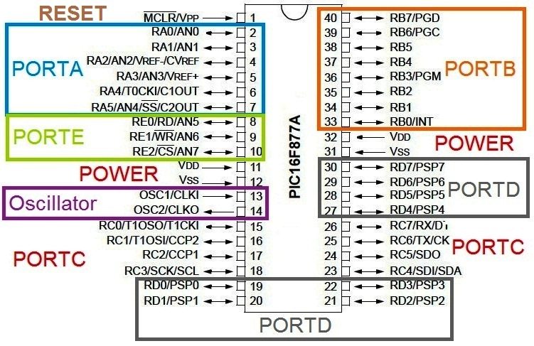
VDD and VSS are the pins for providing power. For PIC 16F877A, VDD = 5V and VSS = GND (0V). Pin 13 & 14, OSC1 and OSC2 are for connecting oscillator which will provide the necessary clock for the operation of microcontroller. The 1st pin MCLR is the reset pin of PIC Microcontroller, it is an active low input. It should be connected to HIGH (VDD) for normal operations. IO (Input Output) pins in a PIC Microcontroller is divided in to different ports, eg : PORTA, PORTB, PORTC, PORTD etc. Each PORT is associated with two registers, TRIS and PORT which are named as TRISA, PORTA, TRISB, PORTB etc.
VDD và VSS là những chân cấp nguồn. Trong PIC16F877A, VDD = 5V và VSS = GND (0V). chân 13 & 14, OSC1 và OSC2 kết nối thạch anh cung cấp xung nhịp cho VDK. chân số 1 MCLR là chân RESET của VDK, nó tác động mức thấp (0V). bình thường nó nên được kéo lênh mức cao (VDD). những chân IO (Input Output) được chia ra các Port : PORTA, PORTB, PORTC, PORTD... một PORT liên quan đến 2 thanh ghi, TRIS và PORT tương ứng TRISA, PORTA, TRISB, PORTB etc.
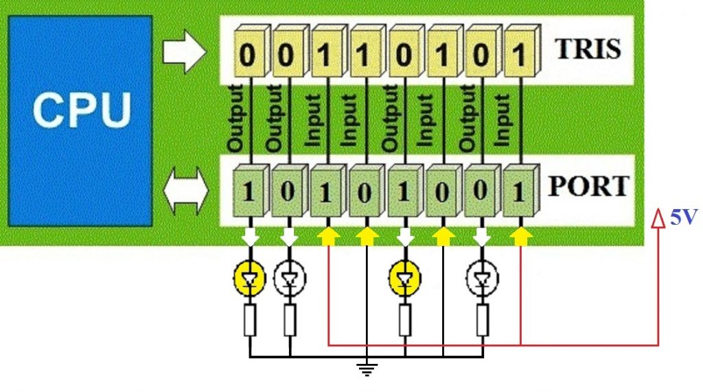
PORT and TRIS are the registers which handle discrete IO operations in PIC Microcontroller. TRIS stands for Tri-state. TRIS register determines the function of an IO pin. Logic 1 at TRIS register makes the corresponding pin Input while Logic 0 at TRIS register makes the corresponding pin Output. PORT register can be used to read input pins or to write status of output pins. For an Output Pin, Logic 1 at PORT register makes the corresponding pin HIGH state (VDD) while Logic 0 at PORT register makes the corresponding pin LOW state (VSS). Reading PORT register reads the actual voltage levels on IO pins. If the actual voltage level is near to HIGH Level (VDD), corresponding PORT bit will be 1 and if the voltage level is near to LOW Level (VSS), corresponding PORT bit will be 0. Hope that you can understand its working from the above image.
Prerequisite Knowledge - Kiến thức tiên quyết
You should know the basics of C Programming for developing projects in CCS C Compiler. Following are some C concepts that may help you.
- A number with a prefix ‘0b’ indicates a binary number.
- A number with a prefix ‘0’ indicates an octal number.
- A number with a prefix ‘0x’ indicates a hexadecimal number.
- A number without a prefix is a decimal number.
Let’s see some examples…
| Decimal | Binary | Octal | Hexadecimal |
|---|---|---|---|
| 0 | 0b00000000 | 00 | 0x00 |
| 1 | 0b00000001 | 01 | 0x01 |
| 128 | 0b10000000 | 0200 | 0x80 |
| 255 | 0b11111111 | 0377 | 0xFF |
CCS C Discrete IO Functions
1. get_tris_x()
This function is used to read TRIS register. Examples are given below.
tris_a = get_tris_A(); //Reads TRISA register
tris_b = get_tris_B(); //Reads TRISB register
2. set_tris_x()
This function is used to write TRIS register. Examples are given below.
set_tris_b(0xFF); //All pins of PORTB as Input
set_tris_c(0x00); //All pins of PORTC as Output
3. input_x()
This function is used to read data from an IO port, ie it returns the value of a PORT register. This function sets a direction of all pins of the specified port as INPUT (TRIS bits 1) before reading the input. Examples are given below.
a = input_a(); //Reads PORTA
b = input_b(); //Reads PORTBc = input_c(); //Reads PORTC
4. output_x()
This function is used to write data to a PORT. This function sets direction of all pins of specified port as OUTPUT (TRIS bits 0) before writing the output. Examples are given below.
output_b(0xFF); //All pins of PORTB HIGH (VDD)
output_c(0x00); //All pins of PORTC LOW (VSS)
5. input()
This function returns the state of the specified pin. This function sets the direction of the specified pin as INPUT (TRIS bit 1) before reading the input. Examples are given below.
while(!input(PIN_B0)); //Waits for Pin B0 to goes HIGH
if(input(PIN_C0))  //Pin C0 is HIGH Now
6. output_bit()
This function writes the specified value (1 or 0) to the specified IO pin. This function sets the direction of the IO pin to OUTPUT before writing the value.
output_bit(PIN_B0, 1); //Makes the pin B0 logic HIGH (VDD)
output_bit(PIN_B7, 0); //Makes the pin B7 logic LOW (VSS)
7. input_state()
This function reads the state of a pin without changing the direction of that pin as input() does.
b0 = input_state(PIN_B0); //Reads the state of B0 without changing its direction
c0 = input_state(PIN_C0); //Reads the state of C0 without changing its direction
8. input_change_x()
This function reads the value of the specified port and it compares with the result of last time input_change_x() function was called. It returns an 8 bit or a 16 bit number representing the changes on the port. A 1 corresponds if the value has changed and 0 corresponds if the value was unchanged.
portc_check = input_change_c();
9. output_float()
This function sets the specified pin to input mode (TRIS bit 1), which is in high impedance state.
output_float(PIN_B3); //Makes pin B3 Input
output_float(PIN_C5); //Makes pin C5 Input
10. output_drive()
This function sets the specified pin to output mode (TRIS bit 0).
output_drive(PIN_B6); //Makes pin B6 output
output_drive(PIN_C3); //Makes pin C3 output
11. output_high()
This function sets the specified pin to HIGH state (VDD).
output_high(PIN_A0); //Makes pin A0 HIGH
output_high(PIN_E0); //Makes pin E0 HIGH
12. output_low()
This function sets the specified pin to LOW state (VSS).
output_low(PIN_A2); //Makes pin A2 LOW
output_low(PIN_E1); //Makes pin E1 LOW
13. output_toggle()
This function toggles the HIGH/LOW state of the specified pin.
output_toggle(PIN_B1); //Toggles the state of PIN B1
output_toggle(PIN_B2); //Toggles the state of PIN B2
Exp: Circuit Diagram – LED Blinking
CCS C – Starting a New Project
Hope you download CCS C compiler from CCS Website and installed it.
- Open the CCS C Software
- File >> New >> Project Wizard
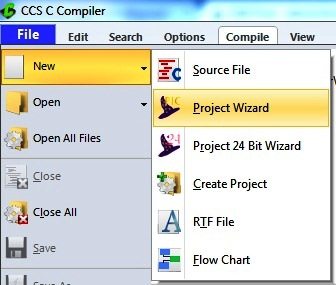
Opening New Project Wizard
- Name the Project
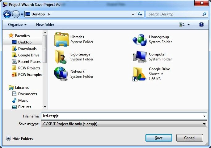
Project Wizard – Save Project As
- Select the device and Set Clock frequency
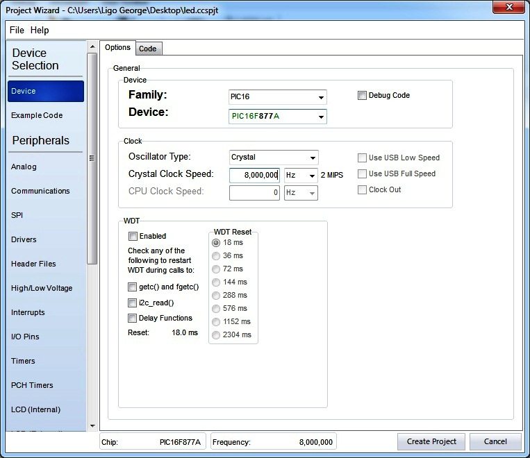
Project Wizard – Select Device and Set Clock Frequency
- Click on Create Project
- The New Project Wizard is completed, now you can see code editor.
- Enter the Code
CCS C Code – LED Blinking
#include <main.h>
#use delay (clock=8000000)
void main(){    output_high(PIN_B0); //LED ON
  while(TRUE)  {    delay_ms(1000);      //1 Second Delay
    output_low(PIN_B0);  //LED OFF}
    delay_ms(1000);      //1 Second Delay  }
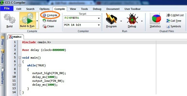
Enter the Code Here – CCS C Editor
- Then click on Compile
- This will generate, hex file in your project folder. This is the file that to be burned to PIC Microcontroller. You can also simulate its working in Proteus ISIS.
![[English] ex viết tắt của từ gì? ex là gì? ex nghĩa là gì?](https://blogger.googleusercontent.com/img/b/R29vZ2xl/AVvXsEhFiRP7spsayG2ppte_20L5qkUrX_HsatNpN8LxoNux1ewEve0IUrCurRVh7VfOvFvrgvnfloMyf_KXZnWfif-BDKLlU5A9zSat0y-Bvu3BeNedpCEJsmMzBTZ-KVRFPfIUZZI60uG8Z5k/s72-c/what-is-ex-meaning.jpg)
![[VI ĐIỀU KHIỂN PIC] - BÀI 6: TIMER/COUNTER CỦA PIC TRONG CCS](https://blogger.googleusercontent.com/img/b/R29vZ2xl/AVvXsEjCz787KDILJfZRV78M_FwKV1KfpbML6oDxg3VEpJgu0t0RJY02ANCf7h2BeqkgD5UgoufjwXLnxGh8Hj1RlBnjlkQYUBrrjUwObg3Ru4lGv0Slpmf1xEjvDJMp5sg425Oaoc_NCuUFqow/s72-c-d/pic-microcontrollers-examples-in-assembly-language-chapter-04-fig4-1.gif)
![[VI ĐIỀU KHIỂN PIC] - BÀI 7: ANALOG (ADC) CỦA PIC TRONG CCS](https://blogger.googleusercontent.com/img/b/R29vZ2xl/AVvXsEiUKGTlRMrOPiQlrL-hvj4au7WA4MEdUChYe_L6bH5mOIDDBpmEBaW_oIKQYz04kfHKY2FmcWb8urcsZgPXMNp5r4ZHqskRjbYNp12JvklYcXHrnweaizv7lKPyribPyxWtsUNzggwXfOI/s72-c/04-06-2017+10-28-24+PM.png)
![[VI ĐIỀU KHIỂN PIC***] - BÀI TẬP MẪU ĐẶC BIỆT CỦA VI ĐIỀU KHIỂN PIC16F877A](https://blogger.googleusercontent.com/img/b/R29vZ2xl/AVvXsEjeSJllTzabiuuA-Zd8LVZY9urJdd-InM0cVOkJtiqrwHcEGJQIajPm7BoERinwbHbEJ2fzFN_P49llQiqF-KyGMuY9NkP5HdA31GAcfcG4WjHdZl2RDngNbMNjts3gpkgib5sVR01eeKc/s72-c/1.png)
![[VI ĐIỀU KHIỂN PIC] - BÀI 9: KHỞI TẠO PWM TRONG PIC 16F877A VỚI CCS](https://blogger.googleusercontent.com/img/b/R29vZ2xl/AVvXsEjerTKUiWHBBUrmBbbOQILAmqhC73Ubt_nYZR9fSu1FCPX2aXz59Ir4kJRIkpphvjOK_Aljt1NCDqHct6fmoeX8JomWvOu06OkZ7fYQvK975ftMf1J4kP8iYpX6P9tPo3NmiSXTS_vUjRY/s72-c/10-06-2017+11-40-42+PM.png)

![[VI ĐIỀU KHIỂN PIC] - BÀI 8: GIAO TIẾP LM35 PIC16F877A TRONG CCS](https://blogger.googleusercontent.com/img/b/R29vZ2xl/AVvXsEgf6kgYQjVzdLTbPiEhjagyXQbubtwplknQ3H2kdg-7T6Di-5_oIpvAGdP3W4DL9sKeSUktz35CKibzHAz7j0eZI5sp1kGnbTYT5bBoy0P7Xv-RPxmUC_SXC9FkrCXS4Kdc3Ob1E7cI0eI/s72-c/HH.png)
![[Research] Cách viết và cấu trúc chi tiết một bài báo khoa học](https://blogger.googleusercontent.com/img/b/R29vZ2xl/AVvXsEiK5FSwIEKPC-QCKmUI_fsFHf3mhlU4GnKEgYQ5vo6SnFVhgOb9iR4_1pCRXk8kuKCQuh9m8xZGH8nDQGO-gsAq5IhT1t5wpHfN3iTLtN45k1UeNG36d1QhMPHPLgpJQntMRPIjb2vwI-0/s72-c/Picture5.jpg)